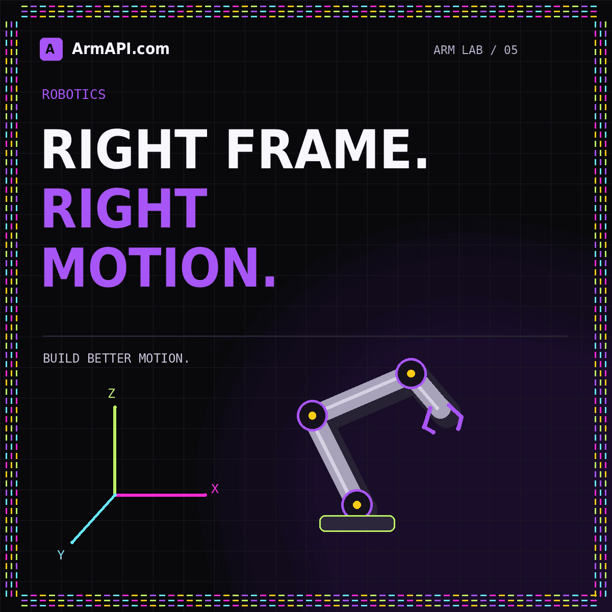
A robot arm position is meaningful only when its reference frame, units, and interpretation are known. Three numbers can describe a point relative to a camera, a robot base, a table, or a tool. They may all be valid numbers while referring to different places. Many integration problems begin when software preserves the values but loses the context that makes them interpretable.
This guide uses a hypothetical two-link planar arm to explain the basic ideas. The geometry is deliberately simplified and does not describe the mechanical structure of the ArmAPI browser illustration. The Robot Arm API overview explains where these concepts fit into a broader command contract. Treat the examples here as a way to reason about interfaces, not as calibration instructions for physical equipment.
Attach a frame and unit to every spatial value
A point should identify the coordinate frame in which it is expressed. For the tabletop example, a target might be described in table_frame while the arm controller expects base_frame. These names represent different origins and axis orientations. Converting between them requires a known relationship; renaming the field does not perform the conversion.
Use consistent units and document exceptions. The ROS REP 103 conventions specify SI-oriented units and right-handed coordinate frames, including a common body convention with x forward, y left, and z up. Those conventions are useful when working within ROS. They do not guarantee that every camera, game engine, or proprietary arm API follows the same choices.
For a boundary between systems, make the conversion explicit and test it with a simple known point. Avoid hidden multipliers and sign changes scattered through rendering code. A single documented adapter is easier to review than many local corrections that happen to make one demonstration look right. Keep the original unit and frame in diagnostic records when practical.
Distinguish a point, a pose, and a joint configuration
A point describes a location. A pose also describes orientation. A joint configuration describes the values of the arm’s joints. These are related representations, not interchangeable payload formats. A gripper may reach a location with several orientations, and some of those orientations may be unsuitable for the intended task even when the position is correct.
For the planar example, two joint angles determine the endpoint’s position under the chosen model. A more complex mechanism may have additional joints and constraints. The application should know whether an operation asks for a specific configuration or a tool pose that a solver must interpret. Naming both targets position without explanation hides a significant difference in responsibility.
Tool orientation also needs a documented representation. Quaternions, rotation matrices, and Euler-angle conventions have different interpretation rules. Do not accept an unlabeled list of four numbers and assume the caller knows the component order. Validate the expected form and reject incomplete or inconsistent values rather than quietly normalizing an unrelated payload into something plausible.
Use forward kinematics to explain where the tool is
Forward kinematics maps a joint configuration through a geometric model to a tool pose. For an ideal planar arm with link lengths L1 and L2 and relative angles q1 and q2, the endpoint is x = L1 cos(q1) + L2 cos(q1 + q2), y = L1 sin(q1) + L2 sin(q1 + q2). This expression follows by adding the two link vectors in a common frame.
A small numerical test makes the model easier to understand. If both angles are zero under this convention, both links extend along the positive x axis, so the endpoint is at L1 + L2 on x and zero on y. Rotating only the first joint rotates the entire chain. These simple cases are valuable tests because the expected result can be checked without trusting a visualization.
The model still depends on assumptions. Link lengths, joint zero positions, axis directions, and the tool attachment must match the mechanism being represented. A correct equation with the wrong model gives the wrong physical answer. Keep model validation separate from confidence in the mathematical implementation.
Understand what inverse kinematics does not guarantee
Inverse kinematics asks which joint values can produce a desired tool pose under a particular model. There may be multiple solutions, no solution, or solutions that are unsuitable for the task. Finding one configuration does not establish that the arm can travel to it through the current environment. A reachable endpoint is not automatically a collision-free route.
For the planar example, some target points can be reached with more than one elbow arrangement. Choosing between them can affect the path and the relationship to nearby obstacles. An interface should therefore make solver assumptions and starting-state context visible rather than returning a mysterious list of angles that appears uniquely correct.
Handle failure explicitly. A solver that cannot find a solution should return a meaningful result, not a fabricated approximation presented as exact. When an application permits an approximate target, document the allowed difference and the evidence used to accept it. The decision belongs to the task requirements, not to an invisible fallback in a convenience wrapper.
Keep transforms connected to time and calibration
A transform relates one frame to another. Some relationships are fixed under the current configuration, while others change as joints move or objects are observed. A camera attached to a moving wrist needs the appropriate transform for the observation time. Combining an older image with a newer joint state can describe a scene that never actually existed.
Represent calibration as a versioned input. If the camera mount or tool attachment changes, previous transforms may no longer be appropriate. Store the relevant calibration identity with test results and saved task definitions. This helps a reviewer determine whether a plan was built against the same geometry that is now in use.
Do not silently bridge missing information. When a required transform is unavailable, stale, or disconnected from the expected frame tree, return a clear error. Guessing identity transforms can make a display look reasonable while moving a target into the wrong location. A visible missing-transform state is much easier to diagnose than a convincing but incorrect picture.
Design interface tests around geometric invariants
Test unit conversions with values whose expected result is obvious. Test frame composition by converting a point through a transform and its inverse, then checking that it returns within the implementation’s chosen numerical tolerance. The tolerance is a software acceptance criterion for that test, not a statement about a robot’s physical accuracy.
Add tests for axis direction, handedness, and tool offsets. A small movement along each named axis should have the documented interpretation in the display. Check an intentionally rotated frame rather than only aligned origins. Many sign mistakes remain hidden when every test point lies on a convenient axis or all transforms are initially identity.
Separate screen coordinates from robot coordinates. A browser canvas often places increasing vertical pixel values downward, while a robot frame may define up as positive. That is a rendering conversion, not a reason to change the underlying robot convention. Keeping the two spaces distinct also makes the simulation easier to port to another renderer.
Label the rendering boundary
Give a renderer an explicit adapter that converts a model-space point into screen coordinates. Test that adapter independently using labeled axes and known points before adding decorative perspective. This keeps the picture useful as a diagnostic tool rather than allowing visual corrections to alter the underlying motion contract. When someone reports that a target appears mirrored, inspect the rendering transform and the robot frame separately. Two sign mistakes can temporarily cancel each other, so an attractive picture is not sufficient evidence that both boundaries are correct.
Conclusion: preserve spatial meaning across every boundary
Coordinate frames and kinematics are not merely mathematical details to hide behind an API. They are part of the contract that makes a motion request understandable. Name the frame, state the units, distinguish poses from joint values, and record the model and calibration context used to interpret them.
Continue with simulation testing to turn these ideas into reproducible checks. For perception-driven workflows, read AI robotic arm planning before trusting an object pose. A strong integration preserves meaning from sensor observation to command record instead of relying on a visualization to make incompatible values appear consistent.


